- Home /
- Resources /
- Learning center /
- Configuring LACP i...
Configuring LACP in vSphere Clusters on Equinix Metal

On this page
This guide creates a vSphere cluster with a networking configuration using LACP LAGs to take advantage of the two physical (server and top-of-rack) ports available on Equinix Metal.
This guide assumes that you have the following set up already:
-
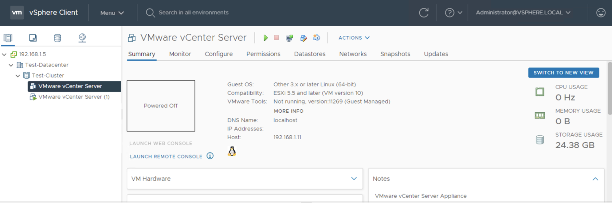
An ESXi server with a vCenter Server Appliance VM, deployed on Equinix Metal.
-
A Layer 2 VLAN provisioned on Equinix Metal, that is connected to your current ESXi server and vCenter Server VM, along with a subnet of local addresses picked out to use on it. This guide uses the
192.168.1.0/24subnet for the Layer 2 VLAN.- The ESXi server running the vCenter Server VM has IP address
192.168.1.11. - The vCenter Server VM is configured with access to the Layer 2 VLAN and has IP address
192.168.1.5, which is the address for the vSphere Client.
- The ESXi server running the vCenter Server VM has IP address
-
A jump host that is on the Layer 2 VLAN and can access all these internal VLAN IPs.
Note: LACP in VMware is only supported on Distributed Virtual Switches therefore it’s not possible to use LACP on standalone ESXi hosts with Standard Virtual Switches.
Part 1 - New Cluster Configuration
Create a vSphere Cluster in vCenter
Log into the vSphere Client that is installed with vCenter Server. It is accessible at the IP address or URL of your vCenter Server Appliance VM.
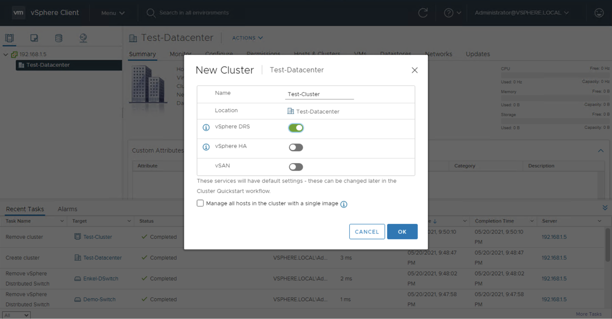
Select your Software Defined Data Center (SDDC) or create one if you haven’t already, our example name is "Test-Datacenter". Click the ACTIONS -> New Cluster. We're only enabling DRS for this test cluster but you can enable HA and vSAN if you want, or you can also enable those feature after the cluster has been created.
Create a Distributed Virtual Switch
Select your SDDC again, then click ACTIONS -> Distributed Switch -> New Distributed Switch. Give it a name and version, then under the Configure Settings section, set the number of uplinks to match your server instance uplinks. Most Equinix Metal server instances come with 2 x 10 Gbps uplinks but there are certain types that come with 2 x 25 Gbps and 4 x 10 Gbps ports. Our example only has 2 uplinks so we're setting the number of uplinks value to 2. You have the option to create a default distributed port group, which is what is shown, you can also create the distributed port group separately.
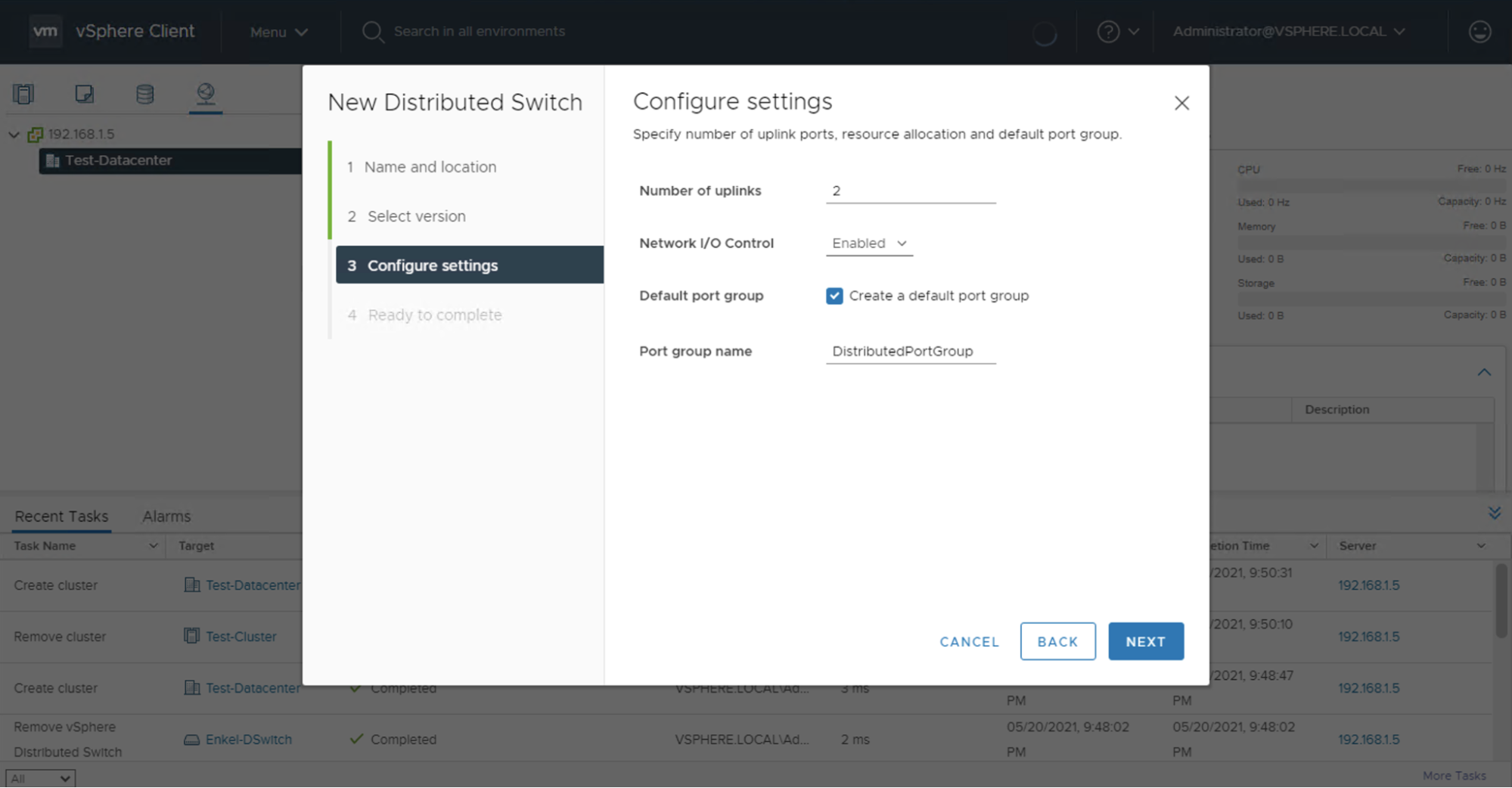
Complete the wizard to create the new Distributed Virtual Switch.
Create an LACP LAG in the Distributed Virtual Switch
To create an LACP LAG, you need to select the newly created Distributed Virtual Switch, then go to the Configure tab, and under the Settings category select LACP.
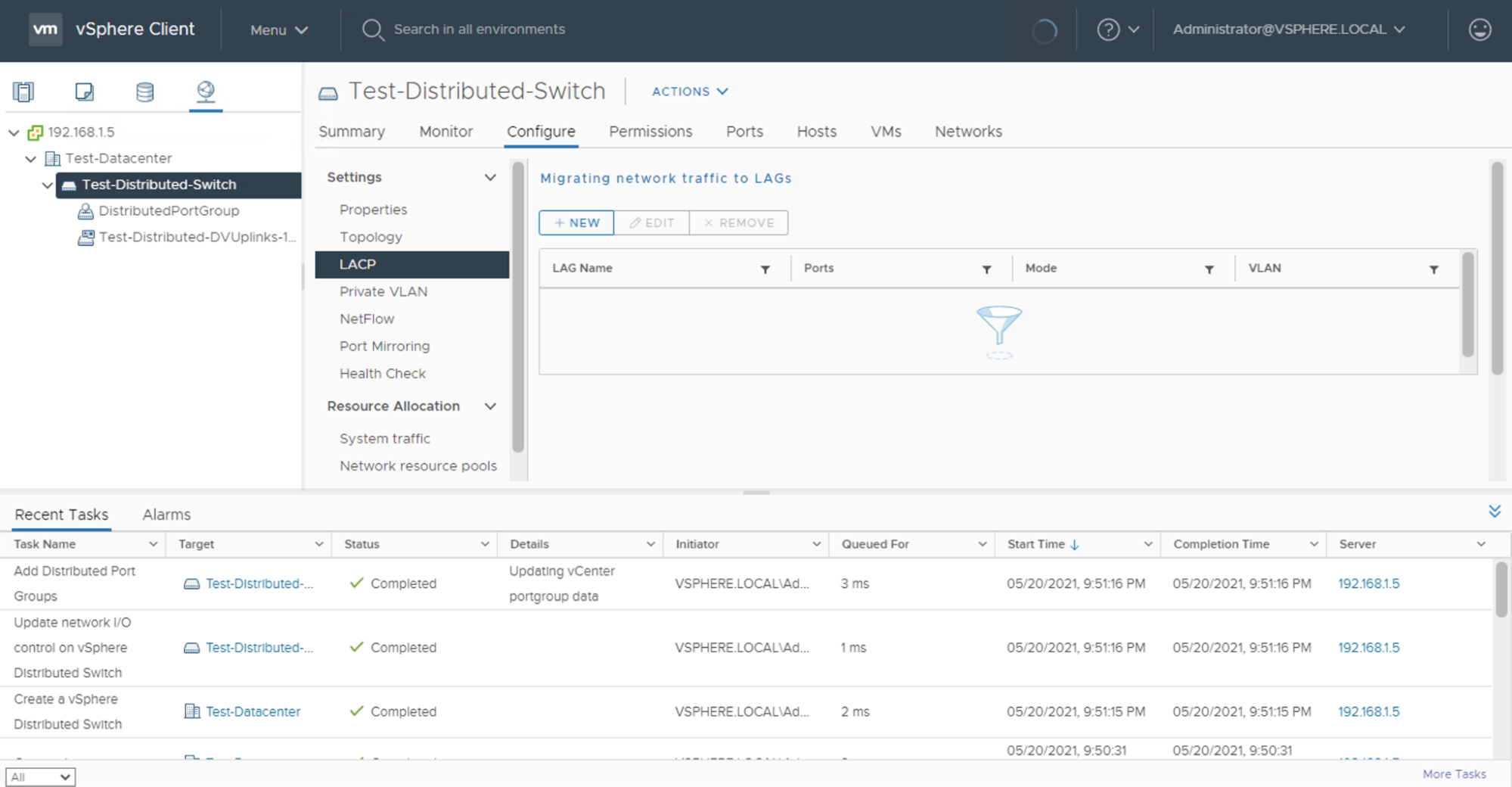
Click the + NEW button to create a new Link Aggregation Group.
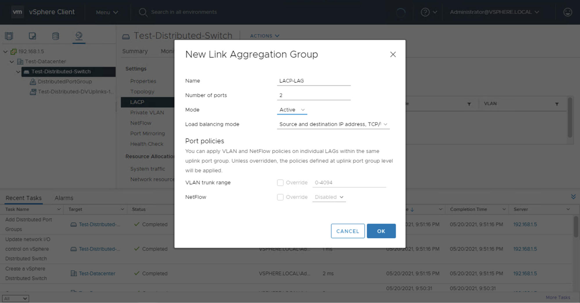
Give it a name, set the number of uplinks to match with your server instance type (2, in the example here). The load balancing rules can be left as default. but you can choose any mode. Then, set mode to Active to match the Equinix Metal top-of-rack switch configuration.
Configure the Distributed Port Group
If you didn’t create a default Distributed Port Group during the Distributed Virtual Switch creation, you will need to create one. To create a distributed port group, select the Distributed Virtual Switch we created earlier, click ACTIONS -> Distributed Port Group -> New Distributed Port Group.
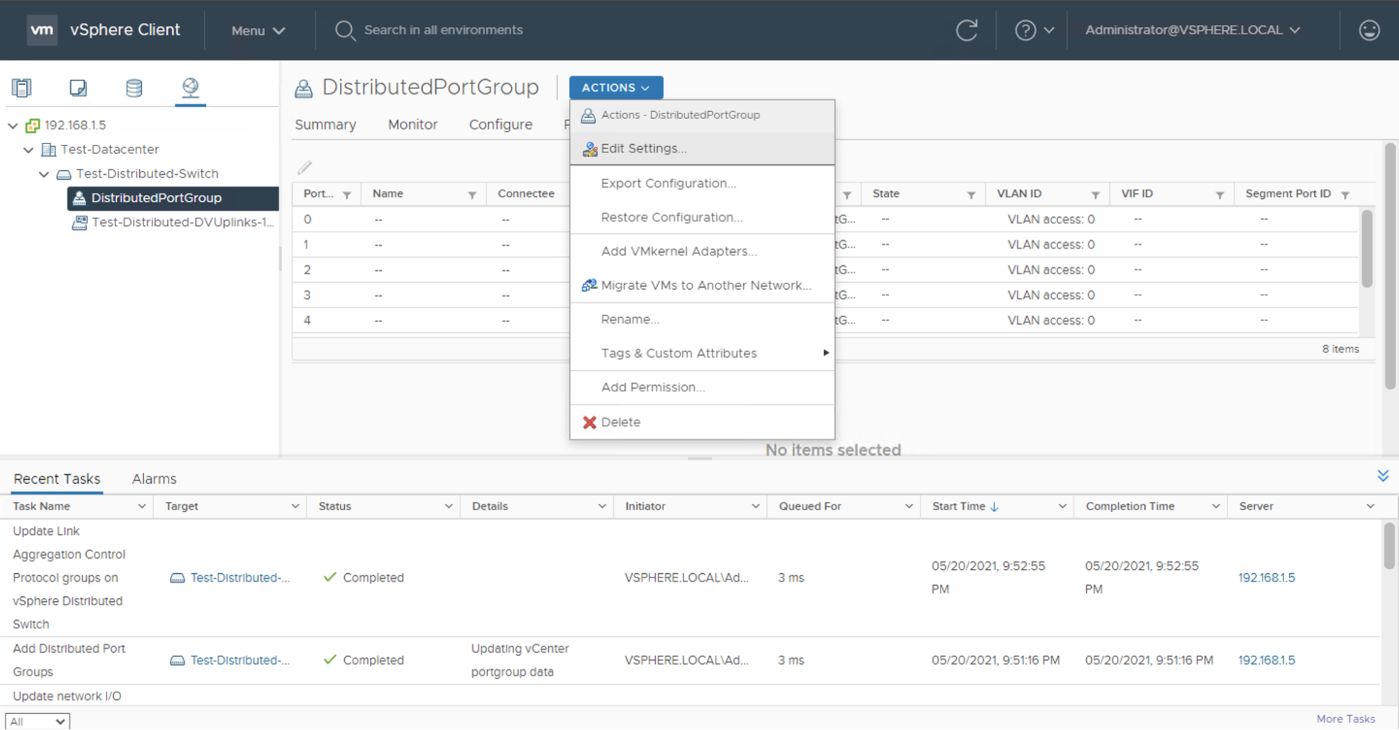
Even if you created the Distributed Port Group previously, there are some configuration setting that you need to adjust. To edit the distributed port group settings, select the Distributed Port Group we created earlier, then click ACTIONS -> Edit Settings.
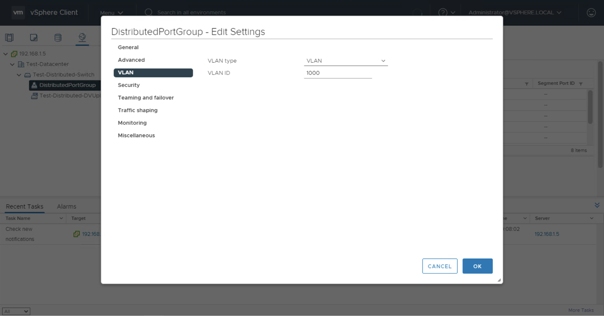
If your VLAN traffic needs to be tagged (for example, if you have multiple VLANs connected to your servers), you must specify the VLAN ID in the distributed port group settings under the VLAN section. Select VLAN from the menu, and change VLAN type to VLAN and set the VLAN ID value to match the Equinix Metal VLAN ID. In our example, the Equinix Metal VLAN ID is 1000, so you would set the VLAN ID value to 1000.
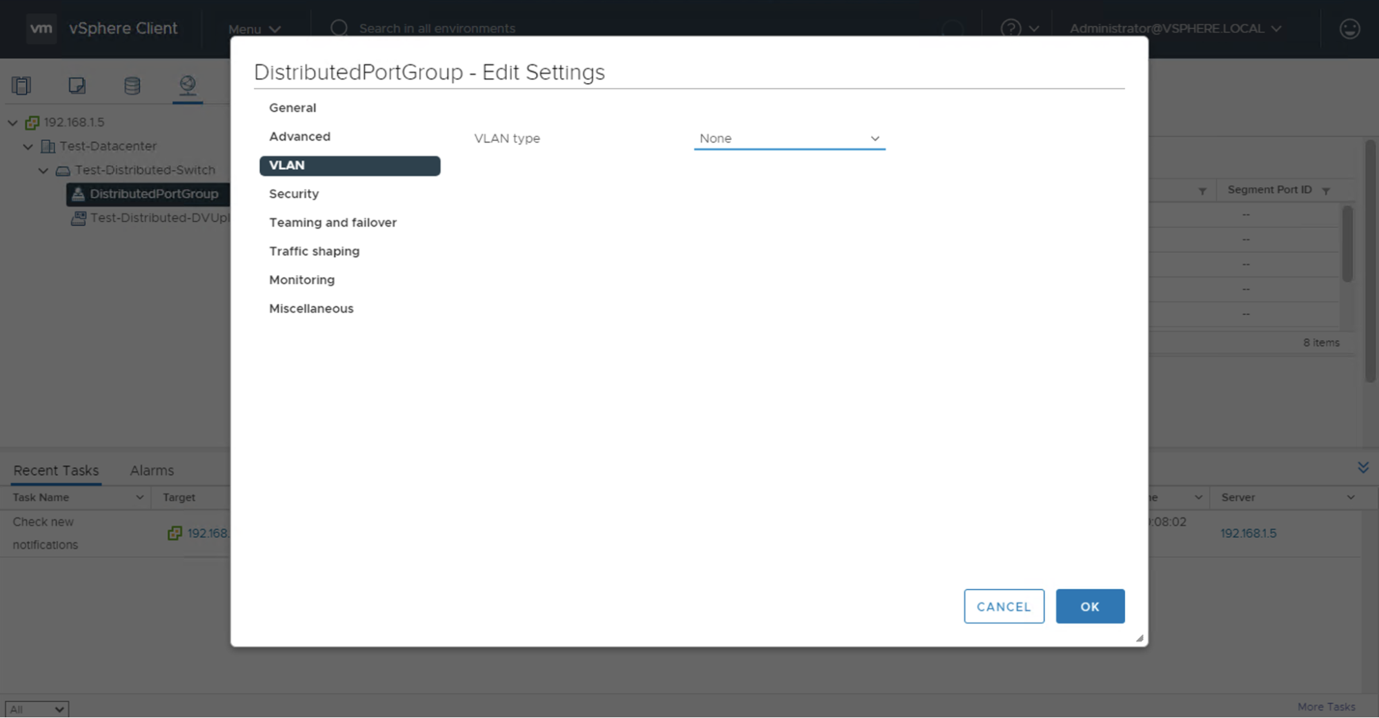
Our current environment only has the single VLAN, so the VLAN traffic is untagged. In this case, you can leave the VLAN type option set to None.
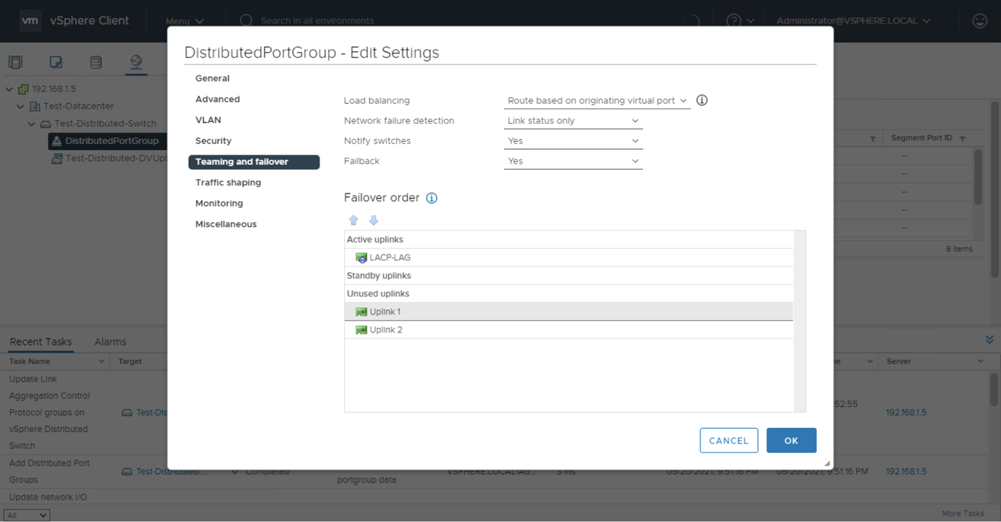
Next, select Teaming and failover. The default failover order of uplinks will appear, where the individual uplinks are under the Active uplinks section and the LACP LAG is under the Unused uplinks section.
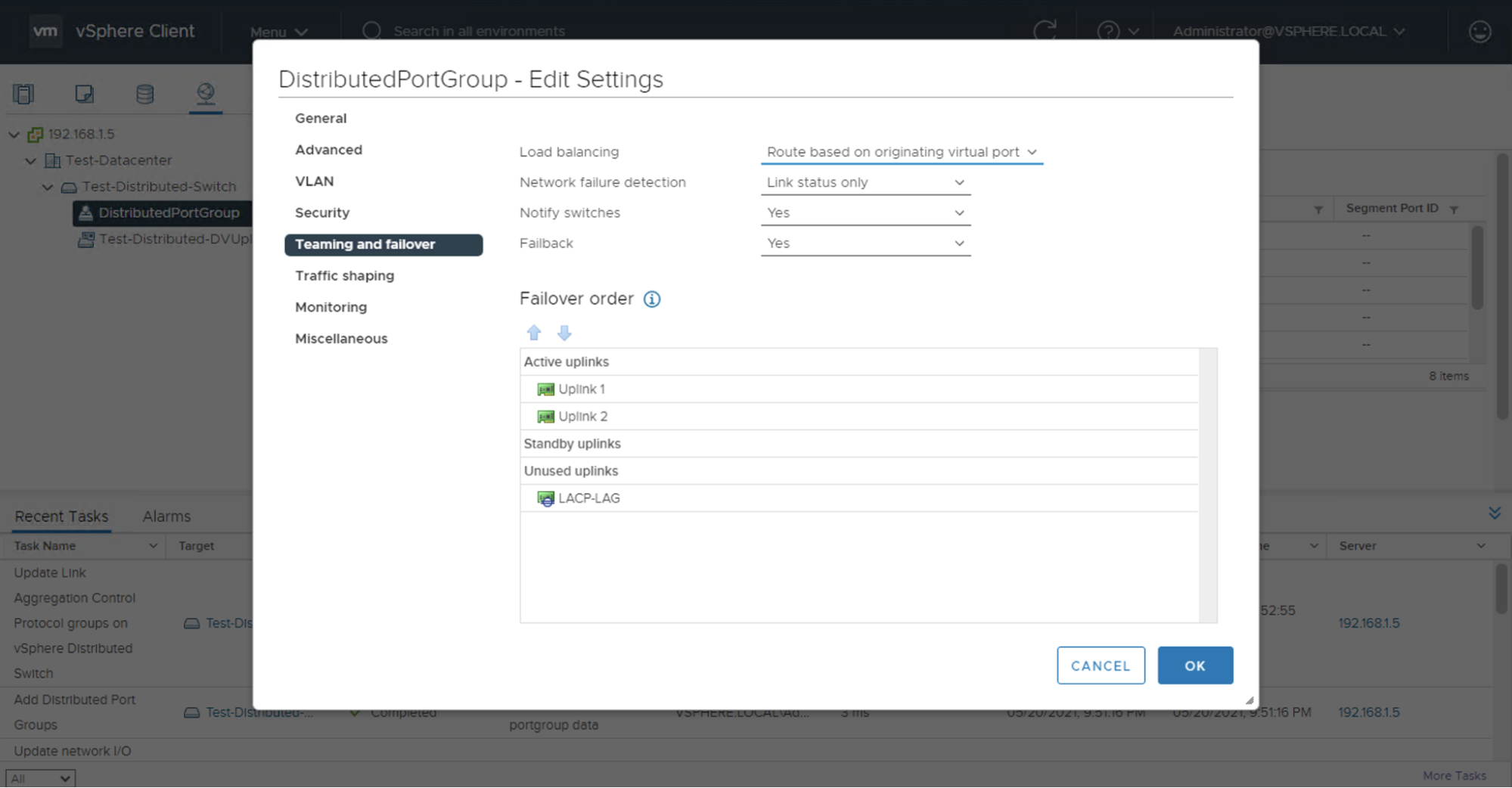
Set the LAG uplink under the Active uplinks section and move the individual uplinks under the Unused uplinks section. This will make it so new nodes that are added to the cluster and distributed switch/port group will create an LACP LAG and utilize that LAG as the active uplink.
Part 2 - Provisioning a New ESXi Server
You're probably going to want to have some some ESXi servers living in your vSphere cluster, so now is a good time to spin one up. If you haven't already provisioned ESXi on Equinix Metal before, or if you just want a quick setup of a fresh server, you can follow the guide for Setting up an ESXi Server, which covers provisioning and networking set up of a new ESXi server that uses private networking and a Layer 2 VLAN to provide access to the Management IP Address.
If you're following along both in that Guide and here, the example internal IP address assigned to the Management WebUI is 192.168.1.31 which is compatible with the 192.168.1.0/24 subnet we're using as an example here.
Part 3 - Configuring the Node in the Cluster
Adding the Node to the Cluster
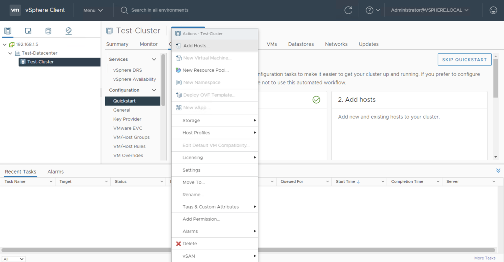
To add our new ESXi server to the cluster, select the cluster on the vSphere Client web UI. Click ACTIONS, then click Add Hosts.
In the new window, add the private IP address of the instance that we set up earlier; for our example instance it's 192.168.1.31. Add the root user credentials, which are initially available in the Equinix Metal portal, but if you set up your server following our ESXi server setup guide, you have hopefully changed them.
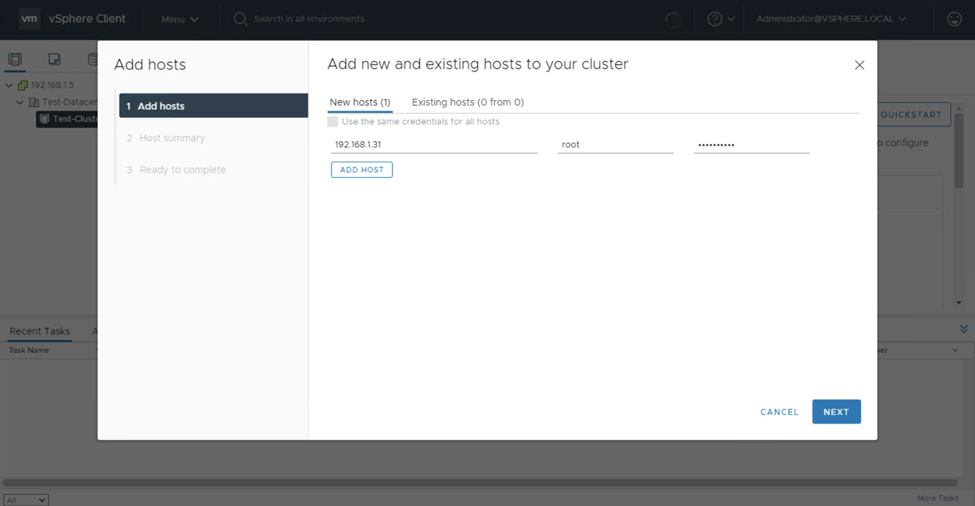
Click Next and finish the wizard. You will see the new instance added to your cluster on the left sidebar of vCenter under the Cluster category.
Adding the Node to the Distributed Virtual Switch
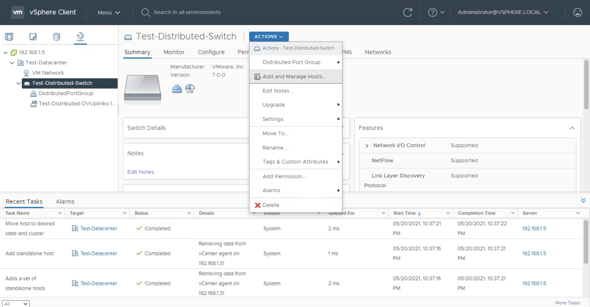
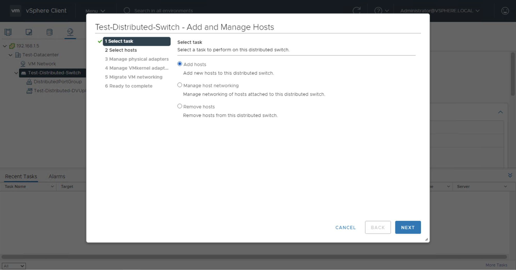
To add the new ESXi server to the distributed virtual switch, select the network category in the vSphere client, select your distributed virtual switch, then click ACTIONS, and Add and Manage Hosts.
The Add and Manage Hosts wizard will appear. Select the Add hosts task.
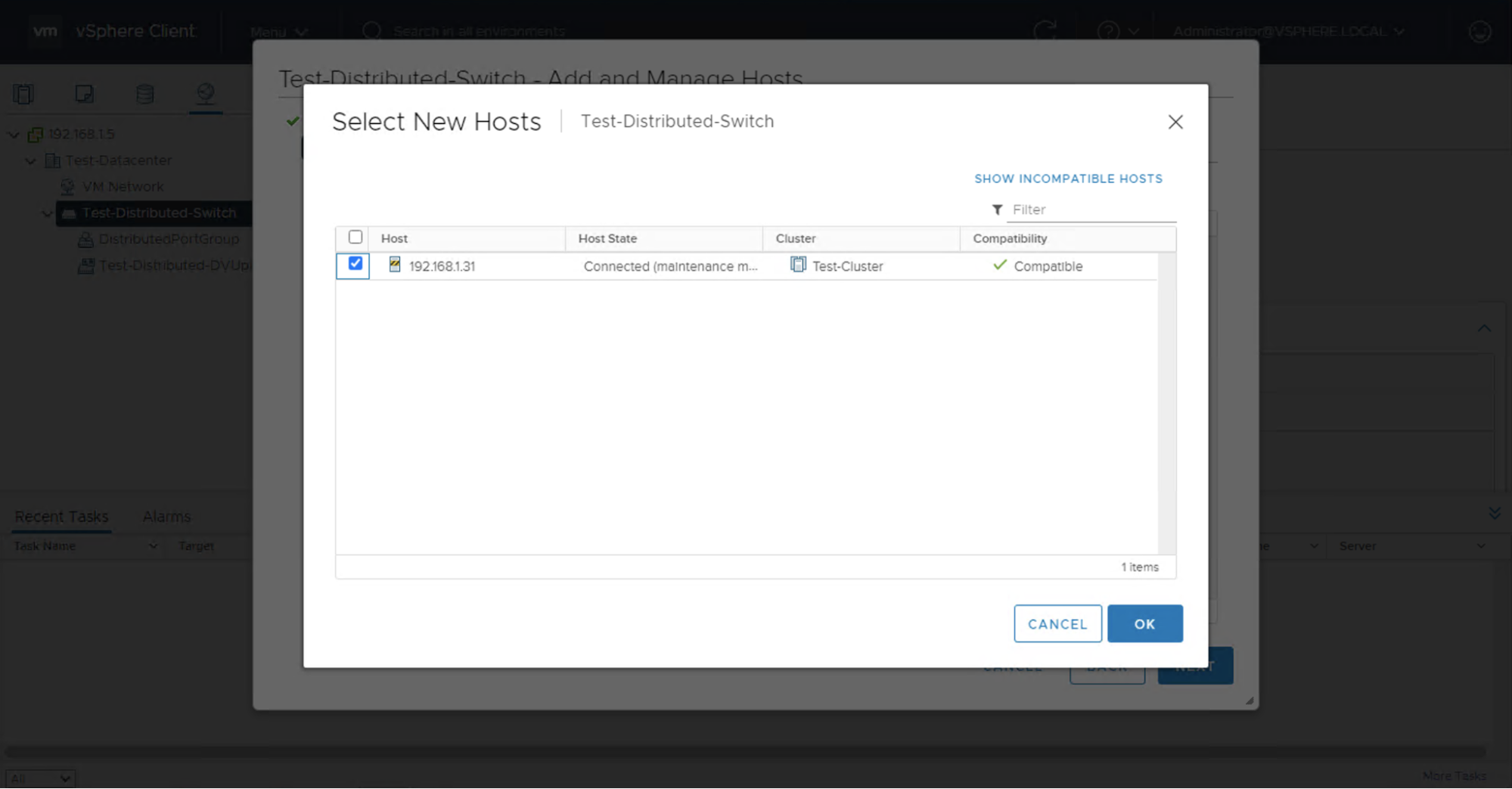
Click + New hosts and select your ESXi server.
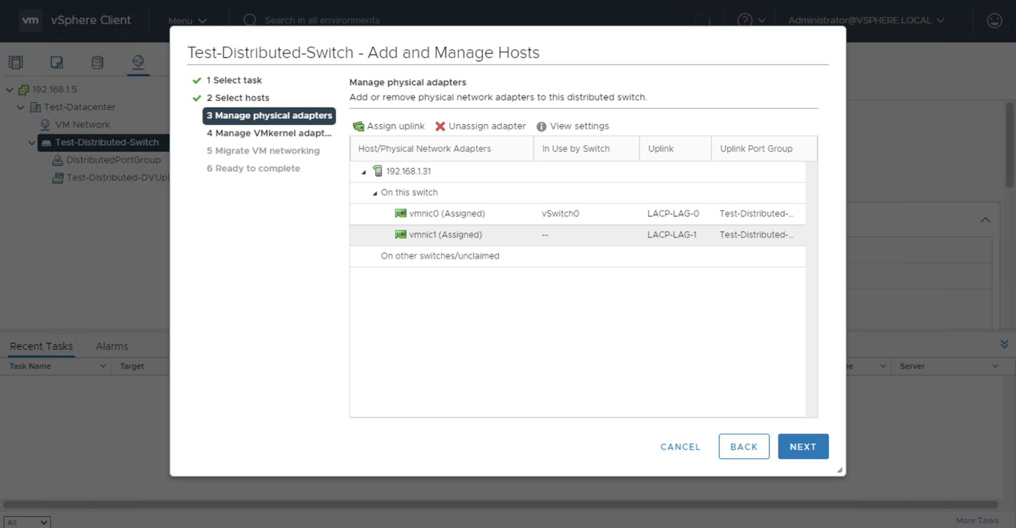
This brings us to managing the physical adapters of the ESXi server. The default setup will have the physical adapters vmnic0 and vmnic1 under the On the other switches/unclaimed category.

Note: depending on the server instance type that you are using, you may see more physical adapters in the list, sometimes the adapters will be unnecessary as they might be the onboard NICs.
From here, you can assign the individual physical adapters to our LACP LAG. Select the vmnic0 physical adapter, then click Assign uplink. On the Select an Uplink screen, there are 2 LAG members. Assign the first physical adapter, vmnic0, to the first member of the LACP LAG which, in the example, is named LACP-LAG-0.
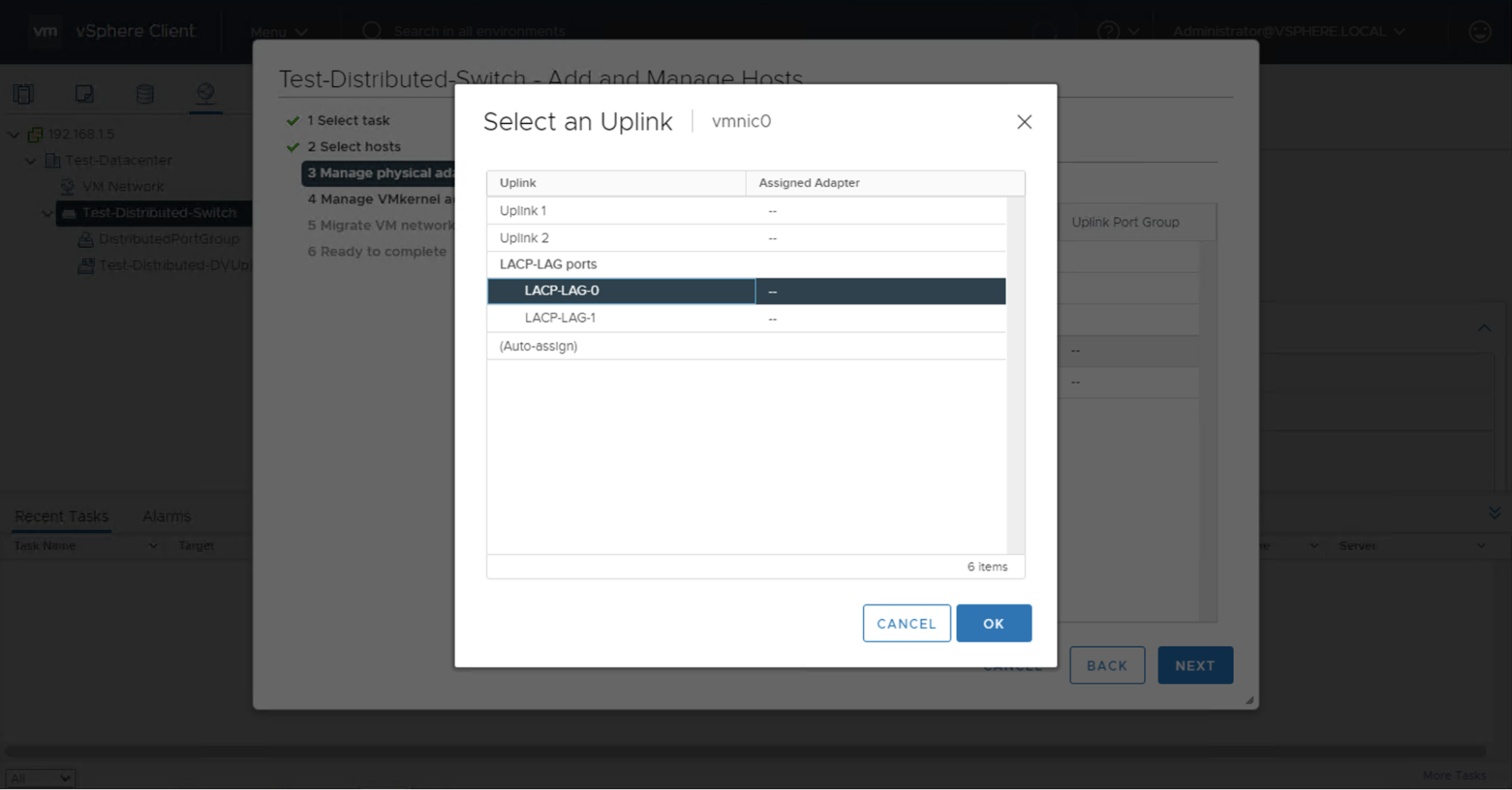
Repeat on the second physical adapter, vmnic1. Select the vmnic1 physical adapter, then click Assign uplink. On the Select an Uplink screen, assign vmnic1, to the other member of the LACP LAG which, in the example, is named LACP-LAG-1.
The final LACP LAG uplinks setup should have each physical adapter assigned to each LACP LAG uplink.
Click Next to advance the wizard and configure the VMkernel adapters. We need to assign each VMkernel adapter to our Distributed Port Group that we created earlier.
Select the first adapter vmk0, then click Assign port group, and choose your Distributed Port Group. Note that the vmk0 VMkernel adapter is under the Management Network port group which serves management traffic such as accessing the ESXi web UI and node communication with the vCenter cluster.
Do the same for the second "vmk1" VMkernel adapter and add it to the Distributed Port Group. These VMkernel adapters can be changed/modified to your liking such as placing them in different port groups. The final setup should have the VMkernel adapters reassigned.

Then click "Next" and you can choose to migrate VM networking or not. If this is a new ESXi server, like in the example, there are probably no VMs running on it to migrate and you can leave Migrate virtual machine networking unchecked. Click Next and finish the setup.
Your node should now be configured with an LACP Link Aggregation Group in Active mode using the 2 physical uplinks connected to the Equinix Metal top-of-rack switch.
Verifying the LACP LAG on the ESXi Server
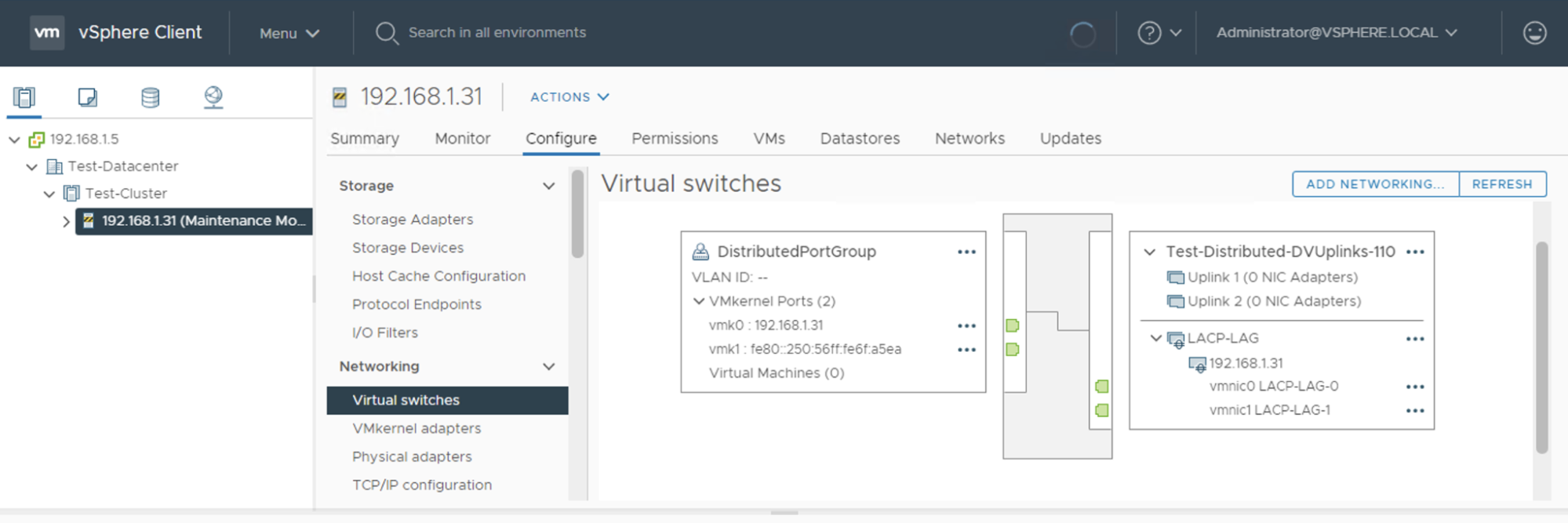
In the vSphere Client, you can verify that the physical server adapters are added to the LACP LAG by selecting your ESXi server in the cluster, and opening its Configure tab. In the Networking section, select Virtual switches. There you will see the 2 physical adapters vmnic0 and vmnic1 that are part of the LACP LAG. If at any time one of the physical uplinks goes down, you will see a red cross sign on the left side of the uplink.
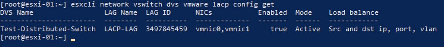
You can also check if LACP is enabled on the ESXi server itself by SSHing into the server and running:
esxcli network vswitch dvs vmware lacp config get
The command returns a table showing the Distributed Virtual Switch, the physical NICs vmnic0 and vmnic1 that are part of the LACP LAG, the LACP mode set to Active, and the load balancing mode. Then LACP configuration is indicated in the Enabled column, being set to true.
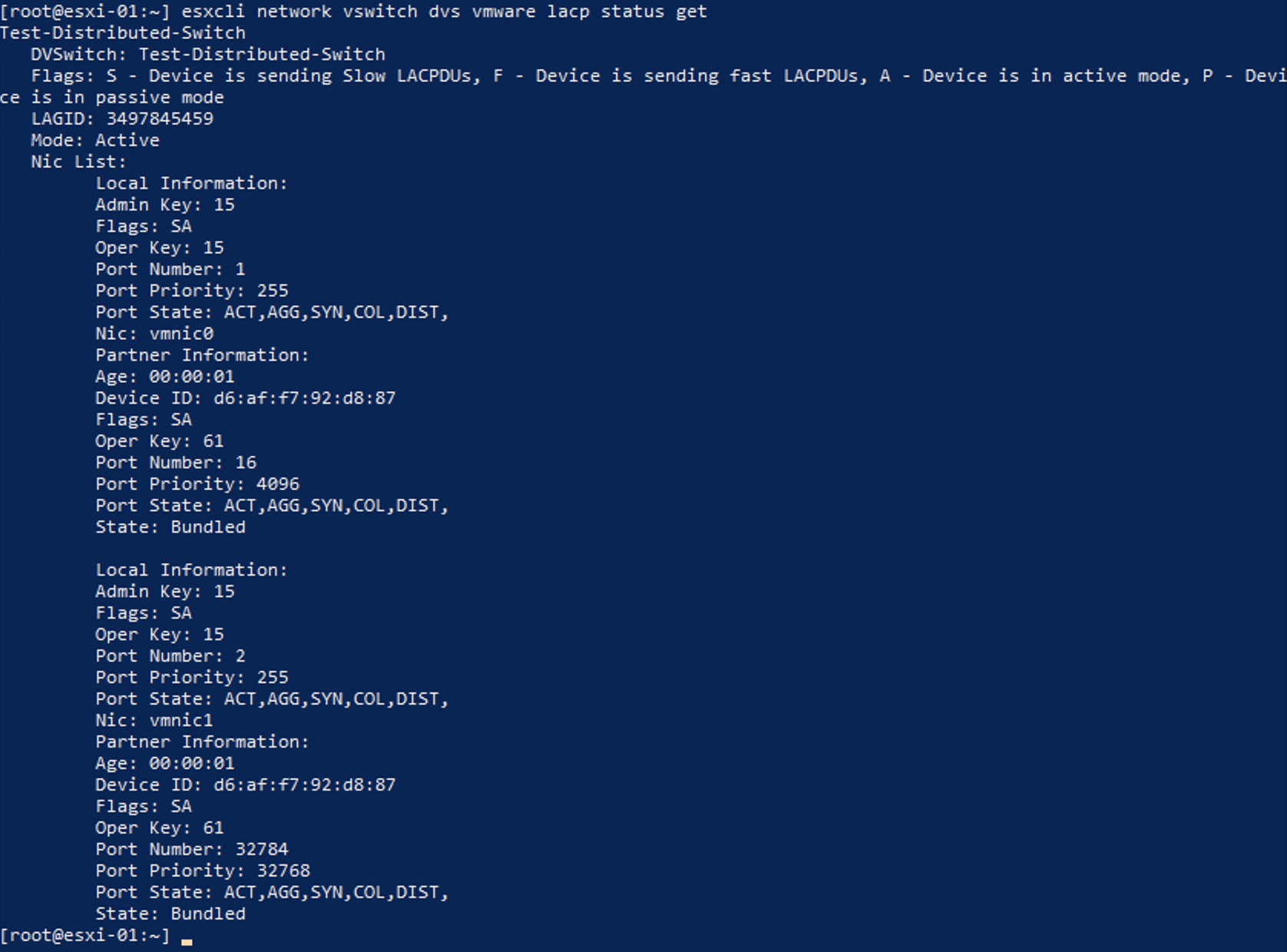
To get more information about the physical NIC adapters and status you can run:
esxcli network vswitch dvs vmware lacp status get
This command shows more detailed information such as the NICs that are part of the LACP LAG along with the state of each NIC, which for this configuration should be Bundled.
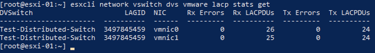
Lastly, you can check LACP Data Unit statistics with:
esxcli network vswitch dvs vmware lacp stats get
It will show the following statistics such as received and transmitted LACP Data Units along with any errors that may occur. Received and Transmitted LACP Data Units show that there is indeed an active LACP LAG session happening between the Equinix Metal server and the top-of-rack switch.
Part 4 - Migrating You vCenter Server to the vSphere Cluster
Now that you have a fresh ESXi server running and configured, you can migrate your vCenter Server VM into the cluster so your control plane is running on the cluster with LACP networking.
First, we need to add the ESXi server running the vCenter Server VM to the cluster but Not add it to the Distributed Virtual Switch. To add our vCenter Server VM to our cluster, log in to the vShpere Client and select the cluster. Click ACTIONS, then click Add Hosts.
Add the private IP address of the vCenter Server Appliance, which in the example is 192.168.1.11, along with the root user credentials for ESXi. Click Next and finish the wizard. You might get a warning about having VMs in a powered on state but that is fine and you can ignore it. Once the new instance is added to your cluster, it will show up on the left sidebar of vCenter under the Cluster category. The vCenter Server VM should also appear on the left sidebar, but you can also find it by selecting the node hosting vCenter and looking at the VMs section.
Next we need to clone the vCenter VM to one of the nodes that is part of the LACP cluster. There are a couple of ways to do this:
- Clone the vCenter VM to a new VM on another node.
- Clone the vCenter VM to a new VM template which we can then use to deploy on another node.
Both methods of cloning the VM are very similar, just ensure that once you clone the VM, you edit the VM hardware so that the VM network adapter is using the Distributed Port Group network instead of the original standard port group that is local to the original node. This example uses method 1 which clones the vCenter VM directly to the ESXi server you previously added to the LACP-configured cluster.
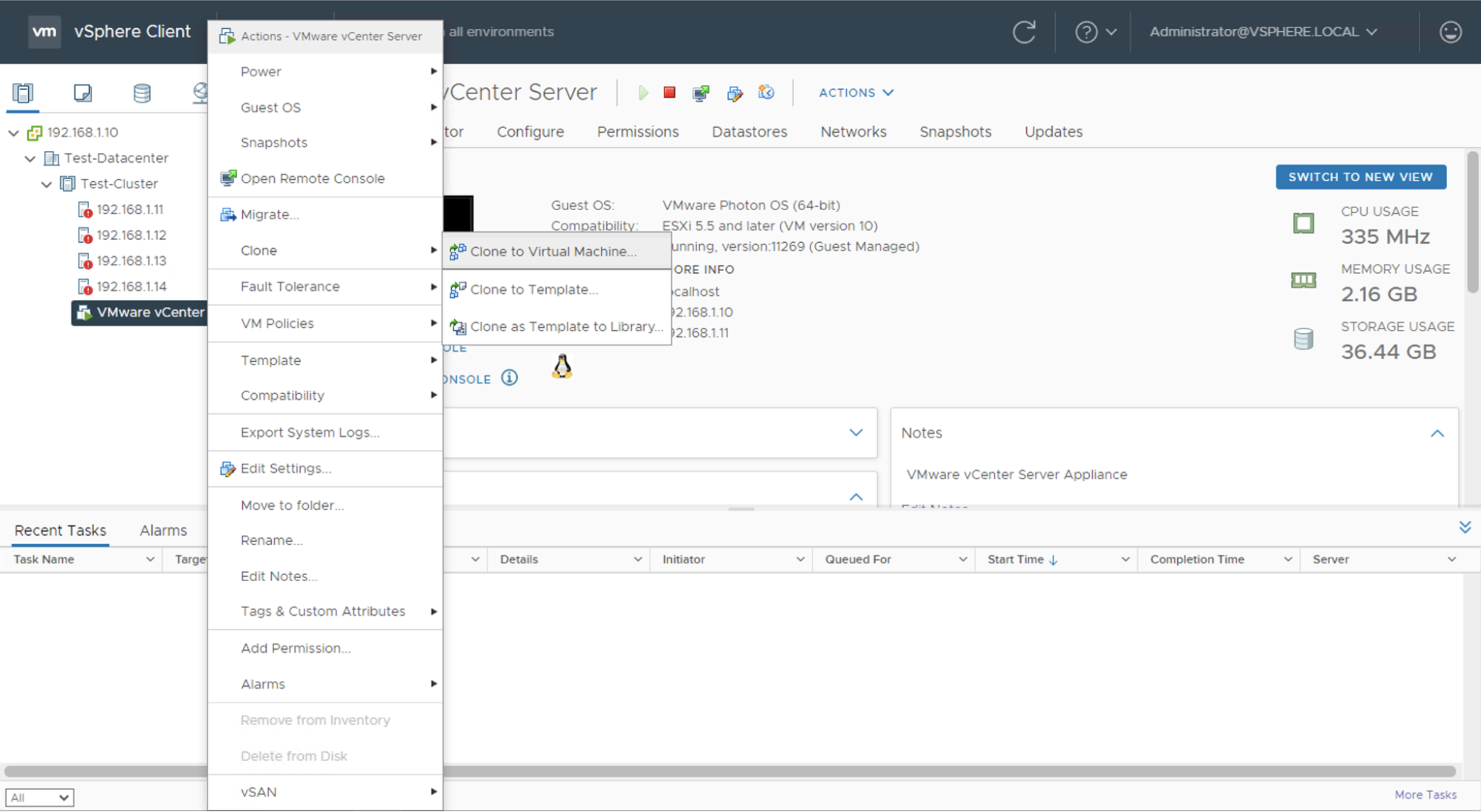
Right click on the vCenter VM, and select Clone -> Clone to Virtual Machine....
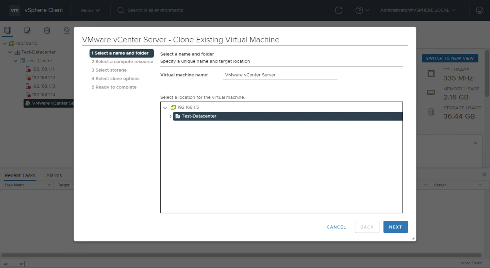
A new wizard will appear that asks you to give the new VM a name. The example uses the same name as the original vCenter Server VM, "VMware vCenter Server". Then, select the SDDC location that the LACP cluster is located in, the example SDDC is named "Test-Datacenter".
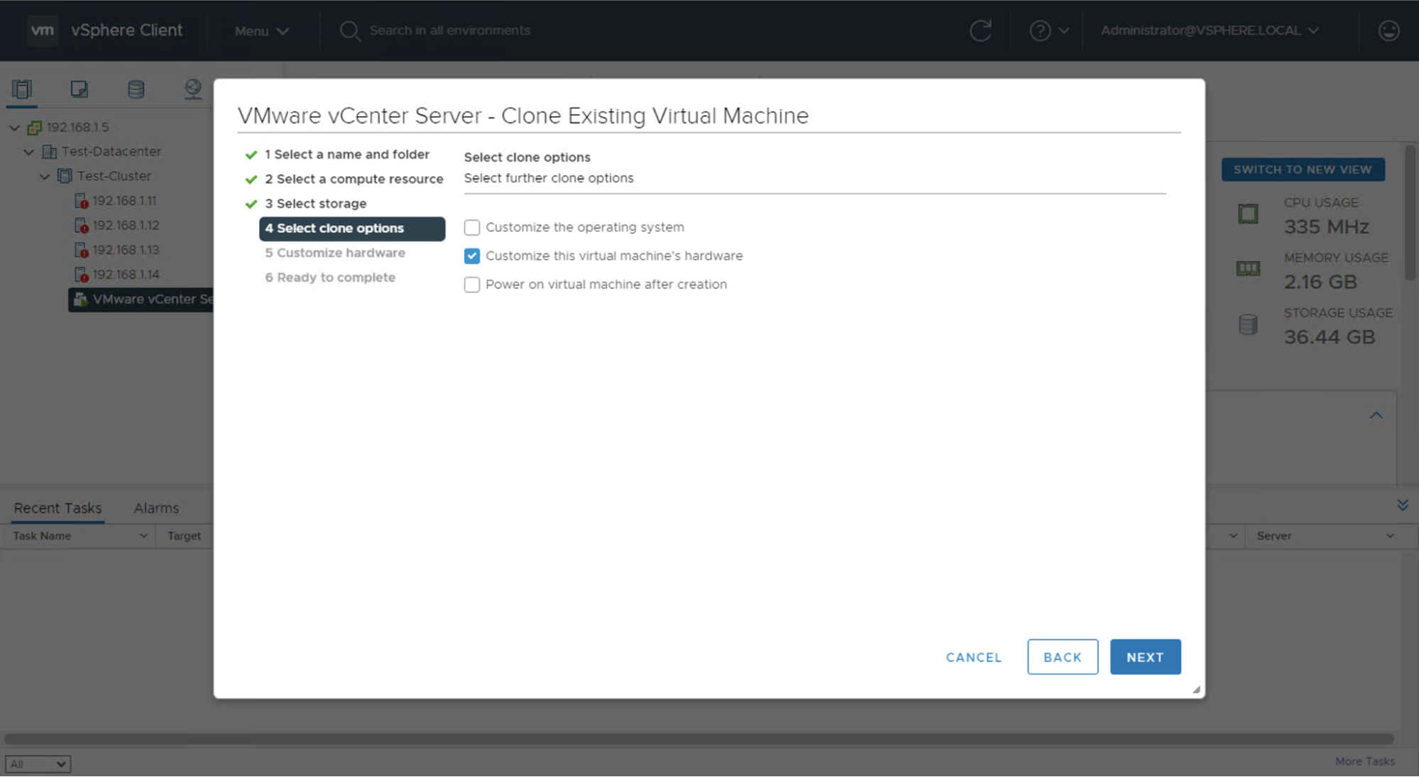
Select an ESXi server that is part of the LACP cluster that will host the new vCenter Server VM, along with a storage datastore. Ensure that the option for Customize this virtual machine’s hardware is selected as you need to change the VM network adapter port group from the original node port group to the Distributed Port Group used in the LACP cluster.
The default VM hardware setting is to place Network adapter 1 in the VM Network port group.
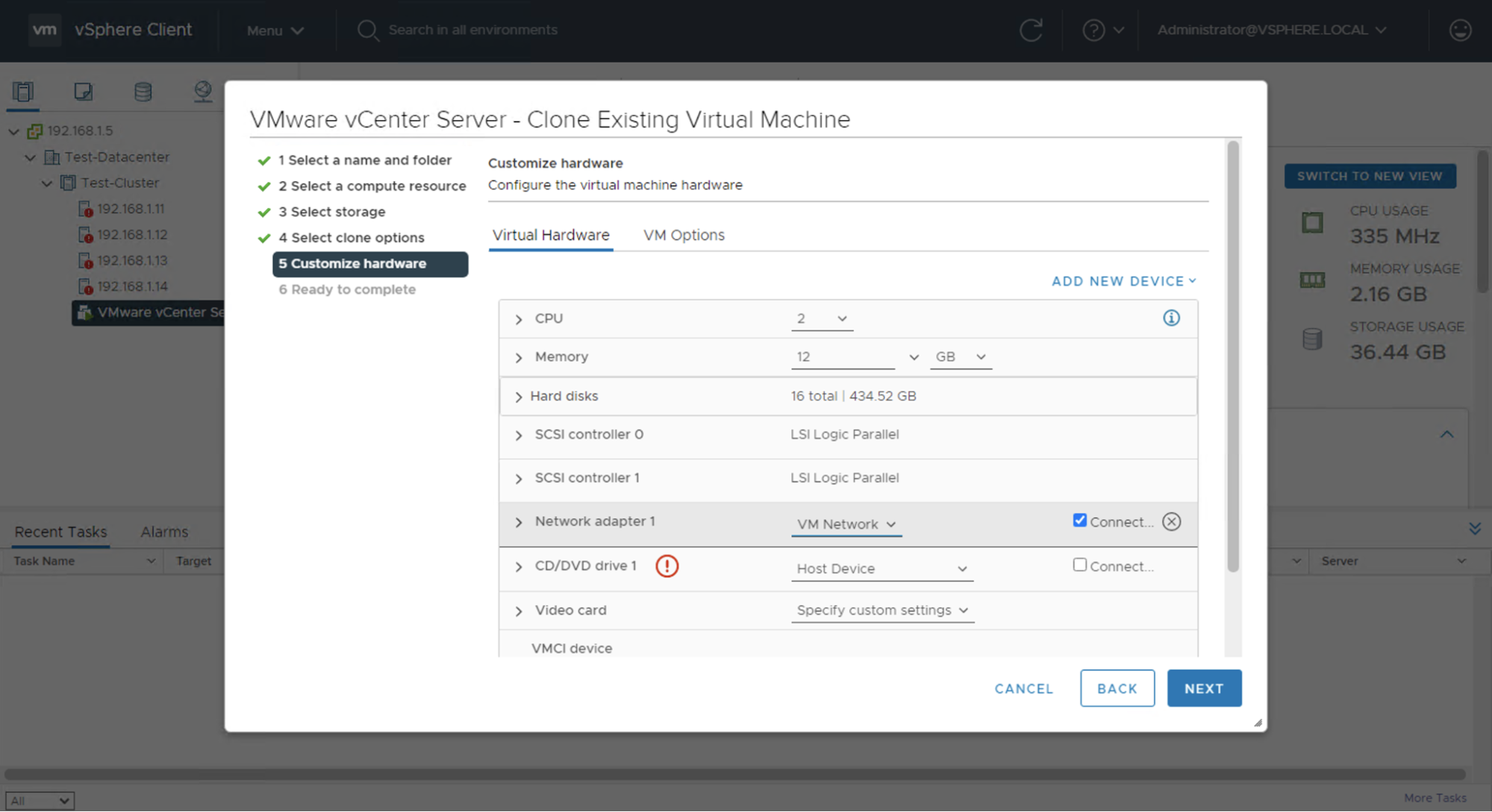
Select the VM Network dropdown -> Browse… -> and choose the Distributed Port Group that is in the LACP cluster and Distributed Virtual Switch.
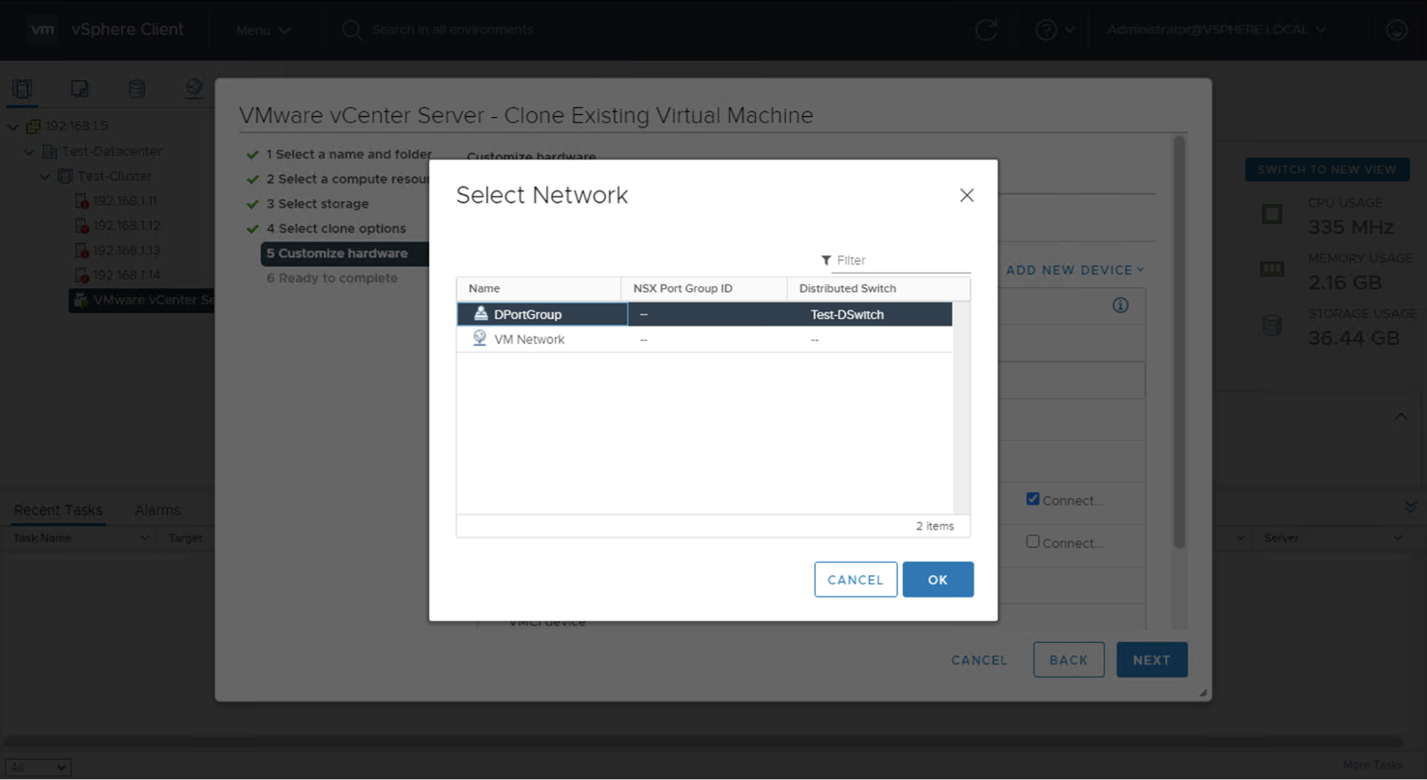
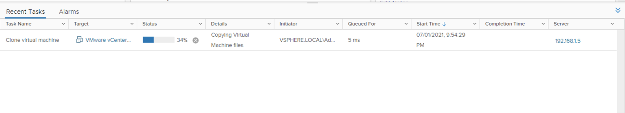
Then leave everything else as they are and finish the clone setup. The VLAN and IP address settings will carry forward to the cloned VM. Once you finish the clone setup, a cloning task will appear that can take a few minutes to complete. The cloned vCenter Server VM will start off in a powered off state.
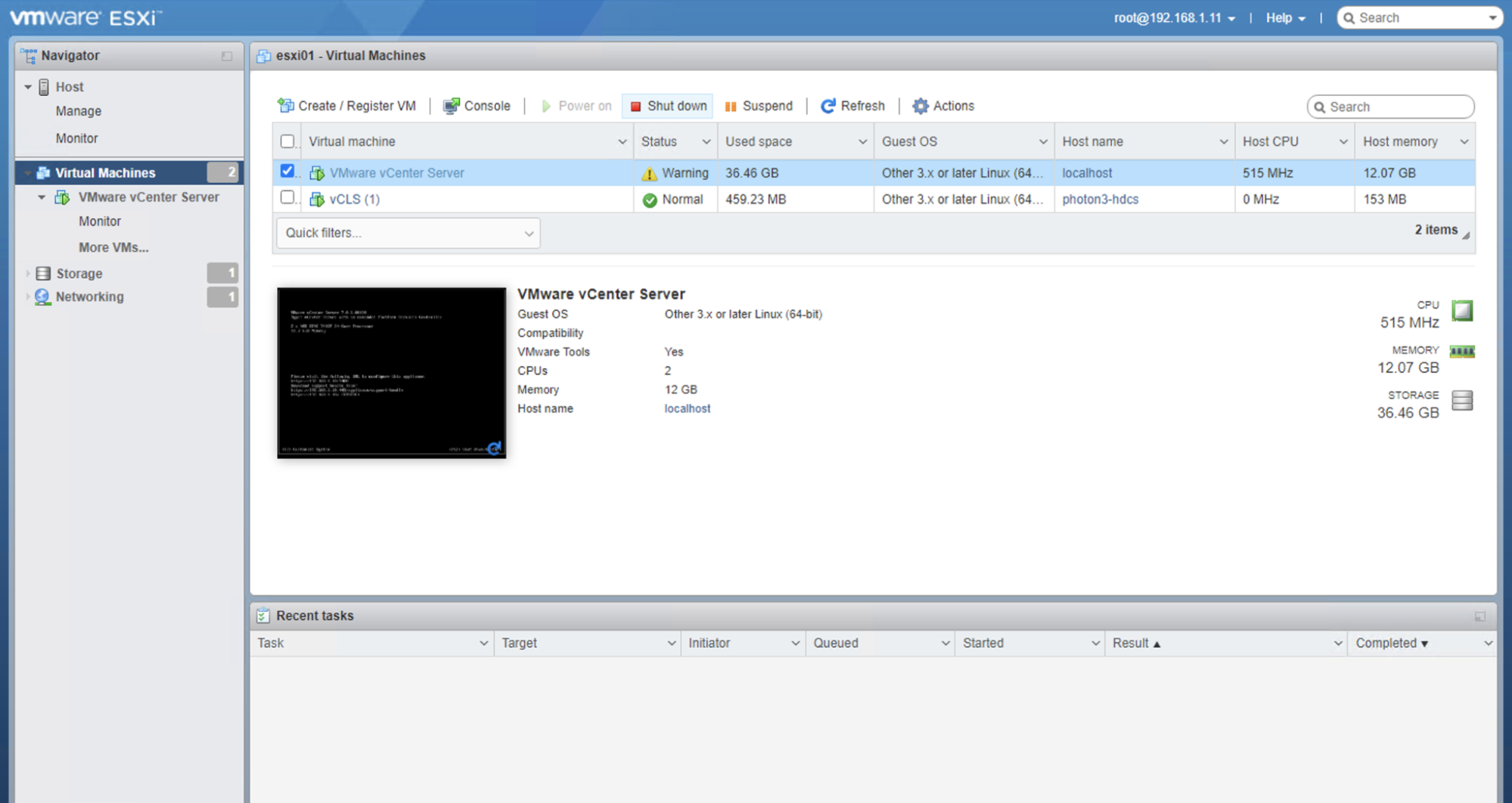
Once the cloning task completes, log out of the vSphere Client and log in to the ESXi Management WebUI that is hosting the original actively running vCenter Server VM. It lives at the IP address of the ESXi server, which in the example is 19.168.1.11. From the ESXi Management WebUI, you can shut down the original vCenter Server VM by selecting it and clicking Shut down. Your cluster will continue running fine because vSphere clusters are designed to function if or when your vCenter Server is unavailable. When you power on vCenter Server on the new VM, it can be used to manage your vSphere cluster from the vSphere client again.
After the first vCenter Server VM is shut down, you can bring up your cloned vCenter Server VM. Log in to the ESXi Management WebUI that is hosting the cloned vCenter Server VM. Select the vCenter Server VM and click Power on.
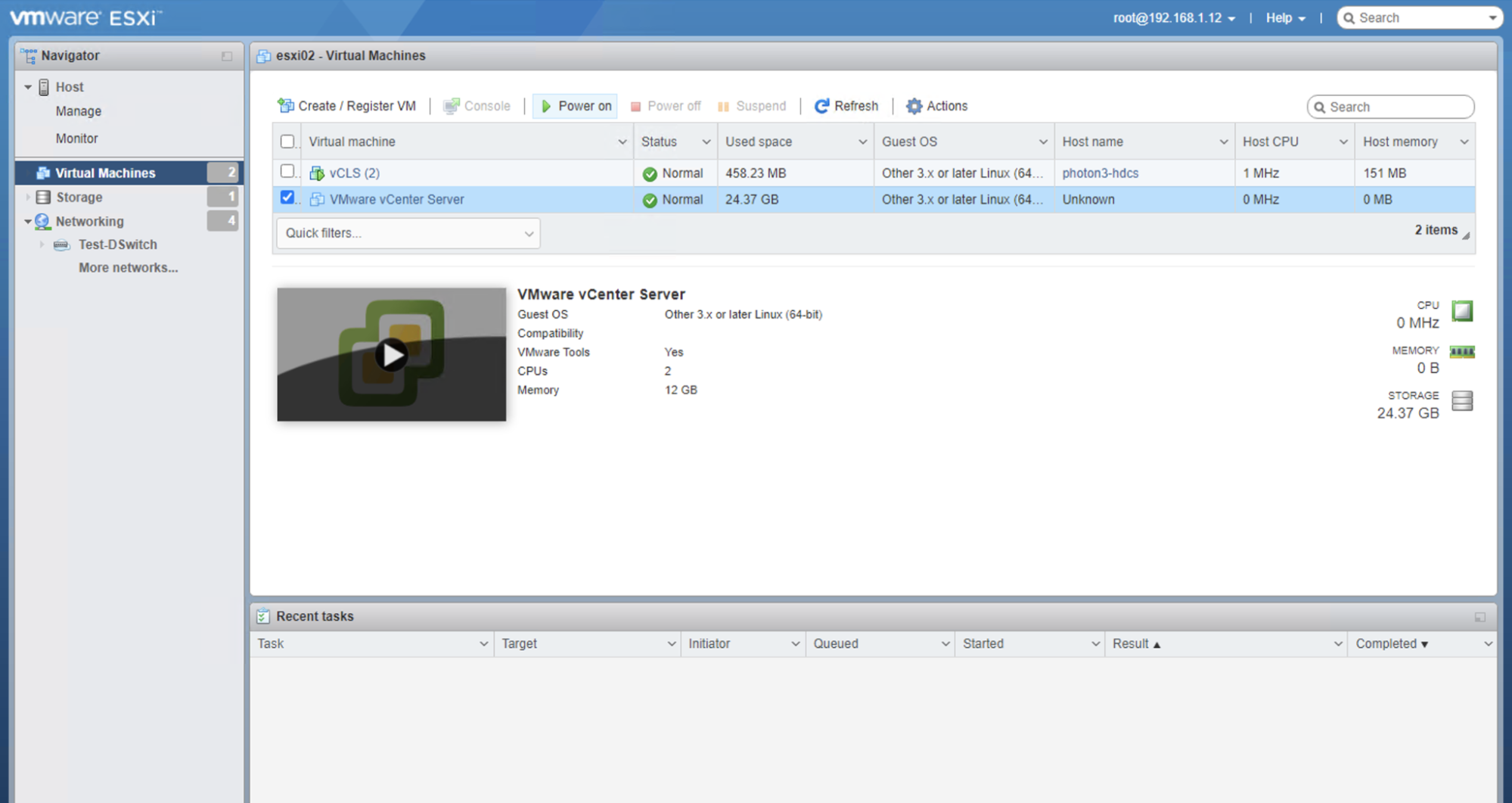
The vSphere Client will take a few minutes to come online after powering on the new vCenter Server VM.
Once the vSphere Client does come back online, and you can log into it, you should see two vCenter Server VMs. One is the old one that is in a powered off state and the other one is the new cloned VM in the new node that is part of the LACP cluster in a powered on state and hosting the current web interface. Note that if you used the same name for both VMs, the new vCenter Server VM will have a "(1)" at the end of the name.
Delete the old vCenter Server VM by right clicking the VM and choosing Delete from Disk. Then rename the new VM right clicking the VM and choosing Rename… to remove the "(1)" at the end of the name.
Your vCenter Server VM should now be successfully migrated and part of the new LACP cluster.
You may also like
Digger deeper into similar topics in our archives
Configuring BGP with BIRD 1.6 on an Equinix Metal Server
Set up BGP on your Equinix Metal server using BIRD 1.6, covering IP configuration, installation, and neighbor setup to ensure robust routing capabilities between your server and the Equinix Metal network.
Configuring BGP with FRR on an Equinix Metal Server
Establish a robust BGP configuration on your Equinix Metal server using FRR, including setting up network interfaces, installing and configuring FRR software, and ensuring secure and efficient IP address announcement.
Crosscloud VPN with Wireguard
Learn to establish secure VPN connections across cloud environments using WireGuard, including detailed setups for site-to-site tunnels and VPN gateways with NAT on Equinix Metal, enhancing cross-platform security and connectivity.
Deploy Your First Server
Learn the essentials of deploying your first server with Equinix Metal. Set up your project & SSH keys, provision a server and connect it to the internet.

Ready to kick the tires?
Use code DEPLOYNOW for $250 credit