- Home /
- Resources /
- Learning center /
- Crosscloud VPN wit...
Crosscloud VPN with Wireguard
Learn to establish secure VPN connections across cloud environments using WireGuard, including detailed setups for site-to-site tunnels and VPN gateways with NAT on Equinix Metal, enhancing cross-platform security and connectivity.

On this page
In the world of VPNs, WireGuard is the new kid on the block. Comparing to other existing VPN protocols, Wireguard offers many advantages, such as reliability, updated encryption, simpler configuration, quicker handshake and faster speeds. This article provides two basic wireguard use cases and the steps to setup the WireGuard VPN in Equinix Metal's facilities.
Use Case#1 - Setup a site-to-site WireGuard VPN tunnel between two Equinix Metal servers located at different Equinix Metal facilities
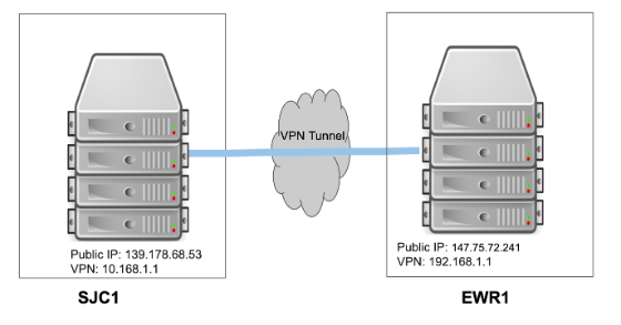
The following diagram illustrates a server at our EWR1 facility and another server at our SJC1 facility and their IP addresses:

Step 1 - Install WireGuard on both Equinix Metal servers (using Ubuntu 18.04 LTS as an example)
Type the following for both servers:
apt-get update
apt-get install software-properties-common -y
add-apt-repository ppa:wireguard/wireguard -y
apt-get install -y wireguard wireguard-dkms wireguard-tools linux-headers-$(uname -r)
After the successful installation, you should see that the /etc/wireguard directory is created for both servers.
Step 2 - Generate public and private keys on both servers
Generate the public and private keys at both server sides:
cd /etc/wireguard
umask 077
wg genkey | tee privatekey | wg pubkey > publickey
The keys will be located at /etc/wireguard/ under the file names of privatekey and publickey
Step 3 - Setup WireGuard interfaces at EWR1 site:
Create a file called /etc/wireguard/wg0.conf on the EWR1 server and add the following content:
[Interface]
PrivateKey = EWR1 server’s privatekey strings
Address = 192.168.1.1
ListenPort = 51820
[Peer]
PublicKey = SJC1 server’s publickey strings
AllowedIPs = 10.168.1.1
Endpoint = 139.178.68.53:51820
Note:
- 192.168.1.1 is a random chosen private IP address for the EWR1 server’s VPN tunnel. Please make sure to NOT use the private IP blocks that’s assigned to your project at EWR1, such as 10.99.x.x/25
- 10.168.1.1 is a random chosen private IP address for the SJC1 server’s VPN tunnel. Please make sure to NOT use the private IP blocks that’s assigned to your project at SJC1, such as 10.88.x.x/25
- 139.178.68.53 is the SJC1 server’s public IP
- 51820 is a random chosen UDP port number
Step 4 - Setup WireGuard Interfaces at SJC1 site:
Create a file called /etc/wireguard/wg0.conf on the SJC1 server side and add the following content:
[Interface]
PrivateKey = SJC1 server’s privatekey strings
Address = 10.168.1.1
ListenPort = 51820
[Peer]
PublicKey = EWR1 server’s publickey strings
AllowedIPs = 192.168.1.1
Endpoint = 147.75.72.241:51820
Note:
- 147.75.72.241 is the EWR1 server’s public IP
- 51820 is a random chosen UDP port number and has to match the port number used for the EWR1 server
Step 5 - Enable & Start WireGuard on both servers
sudo systemctl enable wg-quick@wg0
sudo systemctl start wg-quick@wg0
And ues sudo wg command to double check wg0.conf configuration
Step 6 - Test the VPN using “ping” command
EWR1 server ping SJC1 server and vice versa
ewr1-server # ping 10.168.1.1
PING 10.168.1.1 (10.168.1.1) 56(84) bytes of data.
64 bytes from 10.168.1.1: icmp_seq=1 ttl=64 time=144 ms
64 bytes from 10.168.1.1: icmp_seq=2 ttl=64 time=71.3 ms
^C
sjc1-server # ping 192.168.1.1
PING 192.168.1.1 (192.168.1.1) 56(84) bytes of data.
64 bytes from 192.168.1.1: icmp_seq=1 ttl=64 time=72.6 ms
64 bytes from 192.168.1.1: icmp_seq=2 ttl=64 time=71.3 ms
^C
Use Case 2 - Setup a WireGuard VPN and NAT gateway using a Equinix Metal server
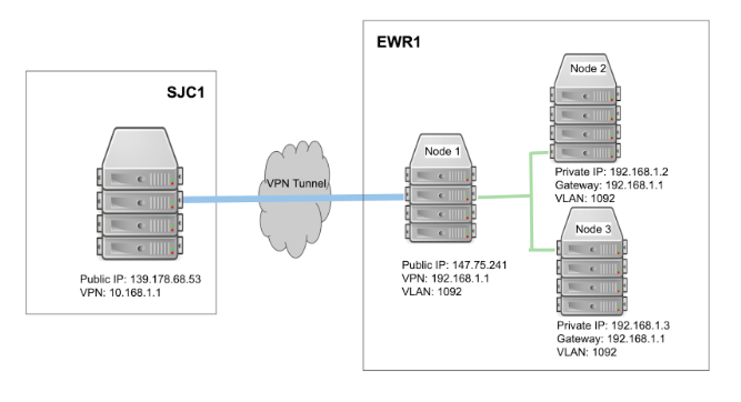
The following diagram illustrates that one server (node 1) at our EWR1 facility serves as a VPN and NAT gateway (internet accessible) and is also on a VLAN (VLAN ID: 1092). Two more servers (node 2, node 3) are on the same VLAN (1092) but have no direct internet access. Another server at our SJC1 facility serves as another VPN gateway.
All traffic between node 2 or 3 in EWR1 and SJC1 server are “forwarded” via node 1 in EWR1 through the WireGuard VPN tunnel between the SJC1 server and EWR1’s node 1.

Step 1 & 2 are the same as use case 1 above
Step 3 - Setup WireGuard interfaces for node 1 at EWR1 side
Create a file called /etc/wireguard/wg0.conf on the EWR1 server and add the following content:
[Interface]
PrivateKey = EWR1 node1 server’s privatekey strings
Address = 192.168.1.1
PostUp = iptables -A FORWARD -i wg0 -j ACCEPT; iptables -t nat -A POSTROUTING -o bond0 -j MASQUERADE
PostDown = iptables -D FORWARD -i wg0 -j ACCEPT; iptables -t nat -D POSTROUTING -o bond0 -j MASQUERADE
ListenPort = 51820
[Peer]
PublicKey = SJC1 server’s publickey strings
AllowedIPs = 10.168.1.1
Endpoint = 139.178.68.53:51820
Note:
PostUp = … enables NAT between the server's public interface (bond0) and the wg0 interface when the wg0 interface is up. PostDown - … disables the NAT when wg0 interface is down.
Step 4 - Setup WireGuard interfaces for SJC1 server
Create a file called /etc/wireguard/wg0.conf on the SJC1 server side and add the following content:
[Interface]
PrivateKey = SJC1 server’s privatekey strings
Address = 10.168.1.1
ListenPort = 51820
[Peer]
PublicKey = EWR1 server’s publickey strings
AllowedIPs = 192.168.1.1
Endpoint = 147.75.72.241:51820
Step 5 - Setup the routing for node 1 of EWR1
Issue the following commands at EWR1 node 1 to enable IPv4 and IPv6 routing, so that it can forward packets for node 2 and node 3:
echo "net.ipv4.ip_forward = 1
net.ipv6.conf.all.forwarding = 1" > /etc/sysctl.d/wg.conf
sysctl --system
Step 6 - Setup VLAN at EWR1
Follow the Equinix Metal guide “layer 2 configuration” to setup the following:
- Create a VLAN at EWR1
- Node 1 is in hybrid mode, i.e. eth0 is on bond0 (internet accessible) but eth1 on layer 2 (on the VLAN 1092 in this example)
- Node 2 and 3 are in layer 2 mode (on the same VLAN as node 1)
Step 7 - Test the VPN and NAT gateway
- EWR1 GW (node 1) ping SJC1 server and vice versa
- Node 2, 3 ping EWR1 GW (node 1) and vice versa
- Node 2, 3 ping SJC1 server and vice versa
Final remarks
The above configurations work just fine across different cloud providers, for example, you can follow the same steps to setup a Wireguard VPN between AWS and Equinix Metal. Besides the two use cases provided in this article, there are many other use cases for WireGuard. For example, kilo uses WireGuard to create a mesh between the different nodes in a Kubernetes cluster.
You may also like
Digger deeper into similar topics in our archives
Configuring BGP with BIRD 1.6 on an Equinix Metal Server
Set up BGP on your Equinix Metal server using BIRD 1.6, covering IP configuration, installation, and neighbor setup to ensure robust routing capabilities between your server and the Equinix...

Configuring BGP with FRR on an Equinix Metal Server
Establish a robust BGP configuration on your Equinix Metal server using FRR, including setting up network interfaces, installing and configuring FRR software, and ensuring secure and efficie...

Deploy Your First Server
Learn the essentials of deploying your first server with Equinix Metal. Set up your project & SSH keys, provision a server and connect it to the internet.

AWS ECS Anywhere on Equinix Metal
Learn to deploy Amazon ECS Anywhere on Equinix Metal.

Ready to kick the tires?
Use code DEPLOYNOW for $300 credit